| XC3000 | XC4000E | XC4000X | XC5200 | XC9000 | Spartan | SpartanXL | Virtex |
|---|---|---|---|---|---|---|---|
| Macro | Macro | Macro | Macro | Macro | Macro | Macro | Macro |


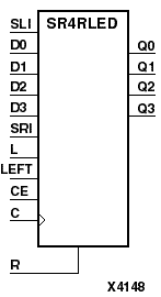
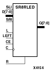
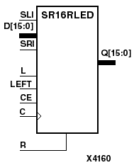
SR4RLED, SR8RLED, and SR16RLED are 4-, 8-, and 16-bit shift registers, respectively, with shift-left (SLI) and shift-right (SRI) serial inputs, parallel inputs (D), and four control inputs - clock enable (CE), load enable (L), shift left/right (LEFT), and synchronous reset (R). The register ignores clock transitions when CE and L are Low. The synchronous R, when High, overrides all other inputs during the Low-to-High clock (C) transition and resets the data outputs (Q) Low. When L is High and R is Low, the data on the D inputs is loaded into the corresponding Q bits of the register. When CE is High and L and R are Low, data is shifted right or left, depending on the state of the LEFT input. If LEFT is High, data on SLI is loaded into Q0 during the Low-to-High clock transition and shifted left (to Q1, Q2, and so forth) during subsequent clock transitions. If LEFT is Low, data on the SRI is loaded into the last Q output (Q3 for SR4RLED, Q7 for SR8RLED, or Q15 for SR16RLED) during the Low-to-High clock transition and shifted right (to Q2, Q1,... for SR4RLED; to Q6, Q5,... for SR8RLED; or to Q14, Q13,... for SR16RLED) during subsequent clock transitions. The truth table indicates the state of the Q outputs under all input conditions.
The register is asynchronously cleared, outputs Low, when power is applied. For CPLDs, the power-on condition can be simulated by applying a High-level pulse on the PRLD global net. FPGAs simulate power-on when global reset (GR) or global set/reset (GSR) is active. GR for XC3000 is active-Low. GR for XC5200 and GSR (XC4000, Spartans, Virtex) default to active-High but can be inverted by adding an inverter in front of the GR/GSR input of the STARTUP or STARTUP_VIRTEX symbol.
| Inputs | Outputs | |||||||||
|---|---|---|---|---|---|---|---|---|---|---|
| R | L | CE | LEFT | SLI | SRI | D3 - D0 | C | Q0 | Q3 | Q2 - Q1 |
| 1 | X | X | X | X | X | X | 0 | 0 | 0 | |
| 0 | 1 | X | X | X | X | D3 - D0 | d0 | d3 | dn | |
| 0 | 0 | 0 | X | X | X | X | X | No Chg | No Chg | No Chg |
| 0 | 0 | 1 | 1 | SLI | X | X | SLI | q2 | qn-1 | |
| 0 | 0 | 1 | 0 | X | SRI | X | q1 | SRI | qn+1 | |
| dn = state of referenced input one setup time prior to active clock transition qn-1 or qn+1 = state of referenced output one setup time prior to active clock transition | ||||||||||
SR4RLED Truth Table
| Inputs | Outputs | |||||||||
|---|---|---|---|---|---|---|---|---|---|---|
| R | L | CE | LEFT | SLI | SRI | D7- D0 | C | Q0 | Q7 | Q6 - Q1 |
| 1 | X | X | X | X | X | X | 0 | 0 | 0 | |
| 0 | 1 | X | X | X | X | D7 - D0 | d0 | d7 | dn | |
| 0 | 0 | 0 | X | X | X | X | X | No Chg | No Chg | No Chg |
| 0 | 0 | 1 | 1 | SLI | X | X | SLI | q6 | qn-1 | |
| 0 | 0 | 1 | 0 | X | SRI | X | q1 | SRI | qn+1 | |
| dn = state of referenced input one setup time prior to active clock transition qn-1 or qn+1 = state of referenced output one setup time prior to active clock transition | ||||||||||
SR8RLED Truth Table
| Inputs | Outputs | |||||||||
|---|---|---|---|---|---|---|---|---|---|---|
| R | L | CE | LEFT | SLI | SRI | D15 - D0 | C | Q0 | Q15 | Q14 - Q1 |
| 1 | X | X | X | X | X | X | 0 | 0 | 0 | |
| 0 | 1 | X | X | X | X | D15 - D0 | d0 | d15 | dn | |
| 0 | 0 | 0 | X | X | X | X | X | No Chg | No Chg | No Chg |
| 0 | 0 | 1 | 1 | SLI | X | X | SLI | q14 | qn-1 | |
| 0 | 0 | 1 | 0 | X | SRI | X | q1 | SRI | qn+1 | |
| dn = state of referenced input one setup time prior to active clock transition qn-1 or qn+1 = state of referenced output one setup time prior to active clock transition | ||||||||||
SR16RLED Truth Table
Figure 10.10 SR8RLED Implementation XC3000, XC4000, XC5200, XC9000, Spartans, Virtex |