
Adding Signals
In order to view signals during the simulation, you must first add them to the Waveform Viewer in the Simulator. The signals are then listed in the Waveform Viewer. You can view and monitor the waveforms next to the corresponding signal names, as well as monitor the state of these signals in the schematic during the simulation.
There are two basic methods for adding signals to the Simulator Waveform Viewer.
- Using Probes from the Schematic Capture tool
- Using the Component Selection window in the Simulator
Adding Signals Using Probes
NOTEThis section only applies to schematic-based design flows. If you are using either the all-VHDL or all-Verilog versions of the watch design, skip to the “Adding Signals Using the Component Selection Window” section .
| In order to add signals for the Watch design simulation, you can use Probes from the Schematic Capture tool to identify signals that you want to view in the Simulator.
- Bring up the Schematic Capture tool from within the Simulator by clicking the SC icon in the Simulator toolbar.

- After the schematic has opened, click the Simulation Toolbox icon in the Schematic Capture toolbar.

This opens the SC Probes toolbox which has several buttons you can use to control the simulation from within the Schematic Capture tool.

NOTEYou can view the results of the simulation either in the Simulator Waveform Viewer or by looking at the annotated values that appear directly on the schematic. These methods are examined more closely later in the tutorial.
|
When the SC Probes toolbox is open, the cursor is automatically put into the Add Probes mode. You can see a probes icon attached to the cursor as shown in the following figure and the Add Probes button in the SC Probes toolbox is depressed. When you are adding probes to the schematic, you must remain in this Add Probes mode.
- With the cursor in Add Probes mode, click once on the CLK signal name on the schematic. A gray box appears to the left of the CLK label. This gray box indicates that a probe has been attached to this signal.
- Repeat Step 3 to add probes to the RESET and STRTSTOP signals and to the TENTHSOUT[9:0], ONESOUT[6:0] and TENSOUT[6:0] buses.
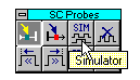
- Return to the Simulator Waveform Viewer by clicking the SIM button in the SC Probes toolbox.
You should now see all of the signals you just probed listed in the Simulator Waveform Viewer.
Adding Signals Using the Component Selection Window
Follow these steps to add more signals using the Component Selection window within the Simulator.
- Click the Component Selection icon in the toolbar in the Simulator or select Signal
 Add Signals.

The Component Selection Window opens.
This window is divided into three panes. The left-most pane is the Signals Selection pane. This pane displays a list of all of the available signals for a given level of hierarchy. The middle pane, Chip Selection, displays a list of all of the components for a given level of hierarchy.
You can select a different level of hierarchy in the right-most pane entitled Scan Hierarchy. For instance, click the OUTS1 macro in the Scan Hierarchy pane. You are now looking at signals and components from the OUTS1 macro in the Signals Selection and Chip Selection panes, respectively.
NOTEBecause Express flattens the design during synthesis, you will only see this OUTS1 component with the schematic version of the design.
| Return to the Root level of hierarchy by clicking the Hierarchy button and then selecting Root in the Scan Hierarchy pane to again view the signals from the top-level of the Watch design.
- This step is divided into two parts, a) and b), for schematic-based design and HDL-based design, respectively.
- Schematic-based design only
In the Signals Selection pane, several signals have red checkmarks next to their names. These signals have already been added to the Simulator, in this case by using probes in the Schematic Capture tool. Now you add more signals to the Waveform Viewer.
From the Signals Selection pane, you can either double click signals to add them to the Waveform Viewer, or you can single click and then press Add. Use whichever method you prefer to add the following buses.
ONES3, ONES0
TENS3, TENS0
NOTEIt is possible to add these signals using probes on the schematic as you did for the other signals, but this process demonstrates the various methods for adding signals.
|
- HDL-based design only
You add signals from the Signals Selection pane to the Waveform Viewer to view them during the simulation. From the Signals Selection pane, you can either double click signals to add them to the Waveform Viewer, or you may single click and then press Add. Use whichever method you prefer to add the following signals.
TENTHSOUT9, TENTHSOUT0
ONESOUT6, ONESOUT0
TENSOUT6, TENSOUT0
CLKINT
STRTSTOP
RESET
If you mistakenly add any signals you do not want to add, you double click them again in the Signals Selection pane to remove them from the Waveform Viewer. The red checkmark should then disappear.
- Close the Component Selection window by clicking the Close button.
All of the signals you added are in the Waveform Viewer.
Deleting a Signal
To delete any of the signals from the Waveform Viewer, first select the signal in the signal list in the Waveform Viewer, right-click, and then select Delete Signals Selected. This operation removes the highlighted signal from the Waveform Viewer.
