The following design illustrates the implementation of a 12-bit to 4-output multiplexer using high level equations.
Design Specifications
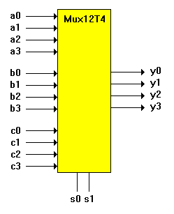
The following figure shows the block diagram for this design. The multiplexer selects one set of inputs and routes that set to the output. The inputs are a0-a3, b0-b3, and c0-c3. The outputs are y0-y3.
The select lines, s0 and s1, control the decoding that determines which set is routed to the output.

Design Method
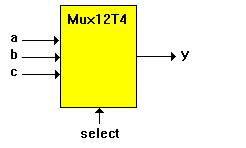
The following figure shows the same multiplexer after sets have been used to group the signals. All of the inputs have been grouped into the sets a, b, and c. The outputs are grouped into set y and the select lines are grouped into set select. The grouping of signals into sets takes place in the declaration section of the source file.
When the sets have been declared, specification of the design is made with the following four equations:
when (select == 0) then y = a;
when (select == 1) then y = b;
when (select == 2) then y = c;
when (select == 3) then y = c;
The relational expression (==) produces an expression that evaluates to true or false, depending on the values of s0 and s1.

In the first equation, this expression is then ANDed with the set a which contains the four bits, a0-a3, and could be written as:
y = (select == 0) & a;
Assume select is equal to 0 (s1=0 and s0=0), so a true value is produced. The true is then ANDed with the set a on a bit by bit basis, which in effect sets the product term to a. If select were not equal to 0, the relational expression inside the parentheses would produce a false value. This value, when ANDed with anything would give all 0s.
The other product terms in the equation work in the same manner. Because select takes only one value at a time, only one of the product terms pass the value of an input set along to the output set. The others contribute 0 bits to the OR gates.
Test Vectors
The test vectors for this design are specified in terms of the input, output, and select sets. Note that the values for a set can be specified by decimal numbers and by other sets. The constants H and L, used in the test vectors, were declared as four bit sets containing all ones or all zeros.
12-to-4 Multiplexer Source File
module Mux12T4
title `12 to 4 multiplexer`
a0..a3 pin;
b0..b3 pin;
c0..c3 pin;
s1,s0 pin;
y0..3 pin;
H = [1,1,1,1];
L = [0,0,0,0];
select = .X. ;
y = [y3..y0];
a = [a3..a0];
b = [b3..b0];
c = [c3..c0];
equations
when (select == 0) then y = a;
when (select == 1) then y = b;
when (select == 2) then y = c;
when (select == 3) then y = c;
test_vectors ([select, a, b, c] -> y)
[ 0 , 1, X, X] -> 1;
``select = 0 a->y[ 0 ,10, H, L] -> 10;
[ 0 , 5, H, L] -> 5;
[ 1 , H, 3, H] -> 3;
``select = 1 b->y[ 1 ,10, 7, H] -> 7;
[ 1 , L,15, L] -> 15;
[ 2 , L, L, 8] -> 8;
``select = 2 c->y[ 2 , H, H, 9] -> 9;
[ 2 , L, L, 1] -> 1;
[ 3 , H, H, 0] -> 0;
``select = 3 c->y[ 3 , L, L, 9] -> 9;
[ 3 , H, L, 0] -> 0;
end

