contents.gifindex.gif

4-Bit Universal Counter

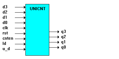
The following design illustrates the implementation of a 4-bit up/down counter with parallel load and count enable. The design is described using high-level ABEL-HDL equations. The following figure shows the block diagram of the counter.
webpack00000015.gif

The outputs q3, q2, q1, and q0 contain the current count. The least significant bit (LSB) is q0.

Using Sets to Create Modes

The counter has four modes of operation:

webpack00090000.gif Load data from the inputs.

webpack00090000.gif Count up.

webpack00090000.gif Count down.

webpack00090000.gif Hold count.

You select the modes by applying various combinations of values to the inputs cnten, ld, and u_d, as described below. The four modes have different priorities, which are defined in the ABEL-HDL description.

Load Mode - Has the highest priority. If the ld input is high, then the q outputs reflect the value on the d inputs after the next clock edge.

Hold Mode - Has the second highest priority. If ld is low, then when the cnten input is low, the q outputs maintain their current values upon subsequent clock edges, ignoring any other inputs.

Up and Down Modes - These have the same (least) priority and by definition are mutually exclusive (only one can be enabled at a time). If cnten is high and ld is low, then when u_d is high the counter counts up and when u_d is low the counter counts down.

Counter Reset

The counter is reset asynchronously by the rst input.

Using Range Operators

Because this design uses range operators and sets, you can modify the counter to be any width by making changes in the declaration section. You could create a 9-bit counter by changing the lines which read ``d3..d0`` and ``q3..q0`` to ``d8..d0`` and ``q8..q0,`` respectively. The range expressions are expanded out and create register sets of corresponding width.

Hierarchical Interface Declaration

Directly after the module name, the design contains a hierarchical interface declaration which is used by the ABEL-HDL compiler and linker if another ABEL-HDL source instantiates this source. The interface list shows all of the input, output, and bidirectional signals (if any) in the design.

Declarations

The declarations contain sections that make the design easier to interpret. The sections are:


Constants
Constant values are defined.

Inputs
Design inputs are declared.

Outputs
The output pin list contains an istype declaration for retargetability.

Sets
The names data and count are defined as sets (groups) containing the inputs d3,d2, d1, and d0, and the outputs q3, q2, q1, and q0, respectively.

Modes
The ``Mode equations`` are actually more constant declarations. First MODE is defined as the set containing cnten, ld, and u_d in that order. Next, LOAD is defined as being true when the members of MODE are equal to X, 1, and X, respectively. HOLD, UP, and DOWN are defined similarly.
Equations

The design of the counter equations enables you to easily define modes and your actual register equations will be easily readable. The counter equation uses when-then-else syntax. The first line:

when LOAD then count := data

uses the symbolic name LOAD, defined earlier in the source file as:

LOAD = (MODE == [X, 1, X])

and MODE itself is a set of inputs in a particular order, defined previously as:

MODE = [cnten, ld, u_d]

The first line of the equation could have been written as follows:

when ((cnten == X) & (ld == 1) & (U-D == X)) then count := data;

which is functionally the same, but the intermediate definitions used instead makes the source file more readable and easier to modify.

4-Bit Universal Counter Source File

module unicnt

interface (d3..d0, clk,rst,ld, u_d -> q3..q0);

title `4-bit universal counter with parallel load`;

``Constants

X,C,Z = .X., .C., .Z.;

``Inputs

d3..d0 pin; ``Data inputs, 4-bits wide

clk pin; ``Clock input

rst pin; ``Asynchronous reset

cnten pin; ``Count enable

ld pin; ``Load counter with input data value

u_d pin; ``Up/Down select - High=up

``Outputs

q3..q0 pin istype `reg`; ``Counter outputs

``Sets

data = [d3..d0]; ``Data set

count = [q3..q0]; ``Counter set

``Mode equations

MODE = [cnten,ld,u_d] ; ``Mode set made of control pins

LOAD = (MODE == [ X , 1, X ]); ``Various modes are defined by

HOLD = (MODE == [ 0 , 0, X ]); ``values applied to control pins.

UP = (MODE == [ 1 , 0, 1 ]); ``Symbolic name may be defined as

DOWN = (MODE == [ 1 , 0, 0 ]); ``a set equated to a value.

Equations

when LOAD then count := data ``Load counter with data

else when UP then count := count + 1 ``Count up

else when DOWN then count := count - 1 ``Count down

else when HOLD then count := count; ``Hold count

count.clk = clk; ``Counter clock input

count.ar = rst; ``Counter reset input

Test_vectors edited...

End