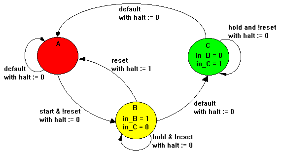
The following design implements a simple sequencer that demonstrates the use of ABEL-HDL state diagrams. The number of state diagram states that can be processed depends on the number of transitions and the path of the transitions. For example a 64-state counter uses fewer terms (and smaller equations) than a 63-state counter. For large counter designs, use the syntax [CountA := CountA + 1] to create a counter rather than using a state machine.

Design Specifications
The following state diagram shows the transitions and the outputs. The state machine starts in state A and remains there until the start input goes high. It then sequences from state A to state B, from state B to state C, and back to state A. It remains in state A until start goes high again. If the reset input is high, the state machine returns to state A at the next clock cycle. If this reset to state A occurs during state B, a halt synchronous output goes high and remains high until start goes high.
During states B and C, asynchronous outputs `in_B` and `in_C` go high to indicate the current state. Activation of the hold input causes the machine to hold in state B or C until hold is no longer high or reset goes high.
Design Method
The sequencer is described by using a STATE_DIAGRAM section in the source file. Constants are declared to simplify the state diagram notation. The two state registers are grouped into a set called sreg and the three states (A, B, and C) are declared with appropriate values specified for each.
The state values chosen for this design allow the use of register preload to ensure that the machine starts in state A. For larger state machines with more state bits, careful numbering of states can dramatically reduce the logic required to implement the design. Using constant declarations to specify state values saves time when you make changes to these values.
The state diagram begins with the STATE_DIAGRAM statement that names the set of signals to use for the state register. In this example, sreg is the set of signals to use. Within the state diagram, if-then-else statements are used to indicate the transitions between states and input conditions that cause each transition. In addition, equations are written in each state that indicate the required outputs for each state of transition.
For example, state A reads:
State A:
in = 0;
in_C = 0;
if (start & !reset) then B with halt := 0;
else A with halt := halt;
This means that if the machine is in state A, and start is high but reset is low, it advances to state B. In any other condition, it remains in state A.
The equations for in_B and in_C indicate that those outputs should remain low while the machine is in state A. The equations for halt, specified using the with keyword, indicate that halt should go low if the machine transitions to state B, but should remain at its previous value if the machine stays in state A.
Test Vectors
The specification of the test vectors for this design is similar to other synchronous designs. The first vector is a preload vector to put the machine into a known state (A), and the following vectors exercise the functions of the machine. The A, B, and C constants are used in the vectors to indicate the value of the current state, improving the readability of the vectors.
3-State Sequencer Source File
module sequence
title `State Machine example`;
q1,q0 pin istype `reg,invert`;
clock,enab,start,hold,reset pin;
halt pin;
in_B,in_C pin;
sreg = [q1,q0];
``State Values ...
A = 0; B = 1; C = 2;
equations
[q1,q0,halt].clk = clock;
[q1,q0,halt].oe = !enab;
state_diagram sreg;
State A:
``Hold in state A until start is active.in_B = 0;
in_C = 0;
IF (start & !reset) THEN B WITH halt := 0;
ELSE A WITH halt := halt.fb;
State B:
``Advance to state C unless reset is activein_B = 1;
``or hold is active. Turn on halt indicatorin_C = 0;
``if reset.IF (reset) THEN A WITH halt := 1;
ELSE IF (hold) THEN B WITH halt := 0;
ELSE C WITH halt :+ 0;
State C:
``Go back to A unless halt is active.in_B = 0;
``Reset overrides hold.in_C = 1;
IF (hold & !reset) THEN C WITH halt := 0;
ELSE A WITH halt := 0;
``test_vectors edited...
end

