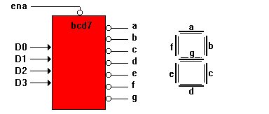
This design illustrates the implementation of a 7-segment display decoder which uses a truth table to decode a 4-bit binary number and display the decimal equivalent on a 7-segment display.
Design Specification
The following block diagram shows a 7-segment decoder and the positions of the display segments. To light a segment, the corresponding line is driven low. When ena is low, the decoder is enabled. When ena is high, all outputs are driven to a high impedance state.

Design Method
The following figure shows the simplified block diagram of the design. The binary inputs and the decoder outputs are grouped into sets (bcd and led). The constants ON and OFF are declared so the design can be described in terms of turning a segment on and off. Because the outputs are active low, ON is declared as 0 and OFF is declared as 1.

The design is described in an equations section and a truth table section. The decoding function is described with a truth table that specifies the outputs required for each combination of inputs. The truth table header names the inputs and outputs. The body of the truth table defines the input to output function.
Because the design decodes a number to a 7-segment display, values for bcd are expressed as decimal numbers, and values for led are expressed with the constants ON and OFF; this makes the truth table easy to understand.
The input and output values could just as easily been described in another form. For example, the line in the truth table:
5 -> [ ON, OFF, ON, ON, Off, ON, ON]
could have been written in the equivalent form:
[0,1,0,1] -> 36
In the second equation the input value (5) is expressed in binary and the output (7 bits) are expressed in decimal notation (ON=0 and OFF=1). Either form of the equation is supported.
7-Segment Display Decoder Source File
module bcd7
title `7-segment display decoder`
`` a BCD to 7-Segment decoder
`` ---
`` f| g |b
`` ---
`` e| d |c
`` ---
D3,D2,D1,D0,Ena pin;
a,b,c,d,e,f,g pin istype `com`;
bcd = [D3,D2,D1,D0];
led = [a,b,c,d,e,f,g];
ON,OFF = 0,1;
``for common anode LED displaysL,H,X,Z = 0,1,.X.,.Z.;
equations
led.oe = !Ena;
@dcset
truth_table (bcd -> [ a, b, c, d, e, f, g ])
0 -> [ ON, ON, ON, ON, ON, ON, OFF]
1 -> [ OFF,ON, ON, OFF,OFF,OFF,OFF]
2 -> [ ON, ON, OFF,ON, ON, OFF,ON ]
3 -> [ ON, ON, ON, ON, OFF,OFF,ON ]
4 -> [ OFF,ON, ON, OFF,OFF,ON, ON ]
5 -> [ ON, OFF,ON, ON, OFF,ON, ON ]
6 -> [ ON, OFF,ON, ON, ON, ON, ON ]
7 -> [ ON, ON, ON, OFF,OFF,OFF,OFF]
8 -> [ ON, ON, ON, ON, ON, ON, ON ]
9 -> [ ON, ON, ON, ON, OFF,ON, ON ]
``test_vectors edited
end

