|
|
|
|
|
|
LogiBLOXs, CORE Generator modules, ABEL modules, and EDIF and XNF files can be instantiated in the VHDL and Verilog code using the “black box instantiation” method.
The Files tab in the Hierarchy Browser does not display the black box module name under the HDL file(s) in which it is instantiated. The Express compiler does not synthesize the black box. It is left as an unlinked cell and resolved in the Translate phase of the implementation.
This section describes how to create HDL designs that instantiate black boxes.
LogiBLOX modules may be generated in Foundation and then instantiated in the VHDL or Verilog code. This flow may be used for any LogiBLOX component, but it is especially useful for memory components such as RAM. Never describe RAM behaviorally in the HDL code, because combinatorial feedback paths will be inferred.
The module being instantiated must be located in the HDL project directory (that is, the directory where the top-level HDL file resides). Running LogiBLOX from the Foundation project ensures this condition is met.
LogiBLOX provides a template tool for generating the VHDL or Verilog component declaration statement.
This section explains how to instantiate a LogiBLOX module into a VHDL design using Foundation. The example described below creates a RAM48X4S using LogiBLOX.
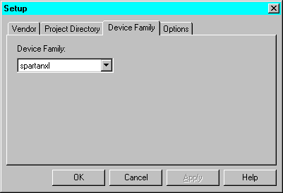
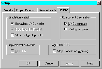
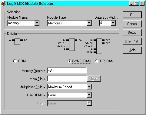
| component_name.ngc | Netlist used during the Translate phase of Implementation | |
| component_name.vhi | Instantiation template used to add a LogiBLOX module into your VHDL source code | |
| component_name.vhd | VHDL file used for functional simulation | |
| component_name.mod | Configuration information for the module | |
| logiblox.ini | LogiBLOX configuration for the project |
-----------------------------------------------

-- LogiBLOX SYNC_RAM Module "memory"

-- Created by LogiBLOX version C.16

--    on Tue Jun 01 16:46:04 1999

-- Attributes

--    MODTYPE = SYNC_RAM

--    BUS_WIDTH = 4

--    DEPTH = 48

--    STYLE = MAX_SPEED

--    USE_RPM = FALSE

-----------------------------------------------

-----------------------------------------------

-- Component Declaration

-----------------------------------------------

component memory

PORT(

A: IN std_logic_vector(5 DOWNTO 0);

DO: OUT std_logic_vector(3 DOWNTO 0);

DI: IN std_logic_vector(3 DOWNTO 0);

WR_EN: IN std_logic;

WR_CLK: IN std_logic);

end component;


-----------------------------------------------

-- Component Instantiation

-----------------------------------------------

instance_name : memory port map

(A => ,

DO => ,

DI => ,

WR_EN => ,

WR_CLK => );
Note: Instead of opening a second sesssion, you could use Edit ![]() Insert File from the HDL Editor tool bar to insert the file into the current HDL Editor session.
Insert File from the HDL Editor tool bar to insert the file into the current HDL Editor session.
library IEEE;

use IEEE.std_logic_1164.all;

use IEEE.std_logic_arith.all;


entity top is

port (          D: in STD_LOGIC; CE: in STD_LOGIC;

              CLK: in STD_LOGIC; Q: out STD_LOGIC;

             Atop: in STD_LOGIC_VECTOR (5 downto 0);

            DOtop: out STD_LOGIC_VECTOR (3 downto 0);

            DItop: in STD_LOGIC_VECTOR (3 downto 0);

         WR_ENtop: in STD_LOGIC;

        WR_CLKtop: in STD_LOGIC);

end top;


architecture inside of top is


component userff

port (    D: in STD_LOGIC; CE: in STD_LOGIC;

        CLK: in STD_LOGIC; Q:  out STD_LOGIC);

end component;


component memory

port (    A:  in STD_LOGIC_VECTOR (5 downto 0);

          DI:  in STD_LOGIC_VECTOR (3 downto 0);

          WR_EN:  in STD_LOGIC;

          WR_CLK:   in STD_LOGIC;

          DO:  out STD_LOGIC_VECTOR (3 downto 0));

end component;


begin


UO:userff port map (D=>D, CE=>CE, CLK=>CLK, Q=>Q);


U1:memory port map(A=>Atop,DI=>DItop,WR_EN=>WR_ENtop,

               WR_CLK=>WR_CLKtop, DO=>DOtop);

end inside;
Note: When the design is synthesized, a warning is generated that the LogiBLOX module is unlinked. Modules instantiated as black boxes are not elaborated and optimized. The warning message is just reflecting the black box instantiation.
This section explains how to instantiate a LogiBLOX module into a Verilog design using Foundation. The example described below creates a RAM48X4S using LogiBLOX.

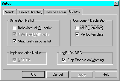

| component_name.ngc | Netlist used during the Translate phase of Implementation | |
| component_name.vei | Instantiation template used to add LogiBLOX module into your Verilog source code | |
| component_name.v | Verilog file used for functional simulation | |
| component_name.mod | Configuration information for the module | |
| logiblox.ini | LogiBLOX configuration for the project |
//---------------------------------------------------

// LogiBLOX SYNC_RAM Module "memory"

// Created by LogiBLOX version C.16

//    on Wed Jun 01 10:40:25 1999

// Attributes

//    MODTYPE = SYNC_RAM

//    BUS_WIDTH = 4

//    DEPTH = 48

//    STYLE = MAX_SPEED

//    USE_RPM = FALSE

//---------------------------------------------------

memory instance_name

( .A(),

  .DO(),

  .DI(),

  .WR_EN(),

  .WR_CLK());


module memory(A, DO, DI, WR_EN, WR_CLK);

input [5:0] A;

output [3:0] DO;

input [3:0] DI;

input WR_EN;

input WR_CLK;

endmodule
Note: Instead of opening a second sesssion, you could use Edit ![]() Insert File from the HDL Editor tool bar to insert the file into the current HDL Editor session.
Insert File from the HDL Editor tool bar to insert the file into the current HDL Editor session.
module top (D,CE,CLK,Q,

            Atop, DOtop, DItop, WR_ENtop, WR_CLKtop);


input D;

input CE;

input CLK;

output Q;


input  [5:0] Atop;

output  [3:0] DOtop;

input  [3:0] DItop;

input WR_ENtop;

input WR_CLKtop;


userff U0  (.D(D),.CE(CE),.CLK(CLK),.Q(Q));


memory U1  (  .A(Atop),

              .DO (DOtop),

              .DI (DItop),

              .WR_EN (WR_ENtop),

              .WR_CLK (WR_CLKtop));

endmodule
Note: An alternate method is to place the module declaration from the .vei file into a new, empty Verilog file (MEMORY.V) and add the new file (shown below) to the project.
//---------------------------------------------------

// LogiBLOX SYNC_RAM Module "memory"

// Created by LogiBLOX version C.16

//    on Wed Jun 01 10:40:25 1999

// Attributes

//    MODTYPE = SYNC_RAM

//    BUS_WIDTH = 4

//    DEPTH = 48

//    STYLE = MAX_SPEED

//    USE_RPM = FALSE

//---------------------------------------------------

module MEMORY (A, DO, DI, WR_EN, WR_CLK);

input [5:0] A;

output [3:0] DO;

input [3:0] DI;

input WR_EN;

input WR_CLK;

endmodule
Note: When the design is synthesized, a warning is generated that the LogiBLOX module is unlinked. Modules instantiated as black boxes are not elaborated and optimized. The warning message is just reflecting the black box instantiation.
CORE Generator COREs may be generated in Foundation and then instantiated in VHDL or Verilog code. COREs can be generated for valid Foundation projects only.
This flow may be used for any CORE Generator CORE. The CORE being instantiated must be located in the HDL project directory (that is, the directory where the top-level HDL file resides). Running LogiBLOX from the Foundation project ensures this condition is met.
This section explains how to instantiate a CORE component into a VHDL design using Foundation.
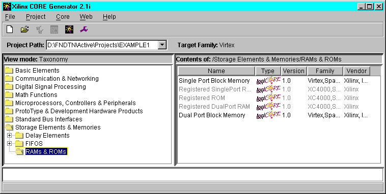
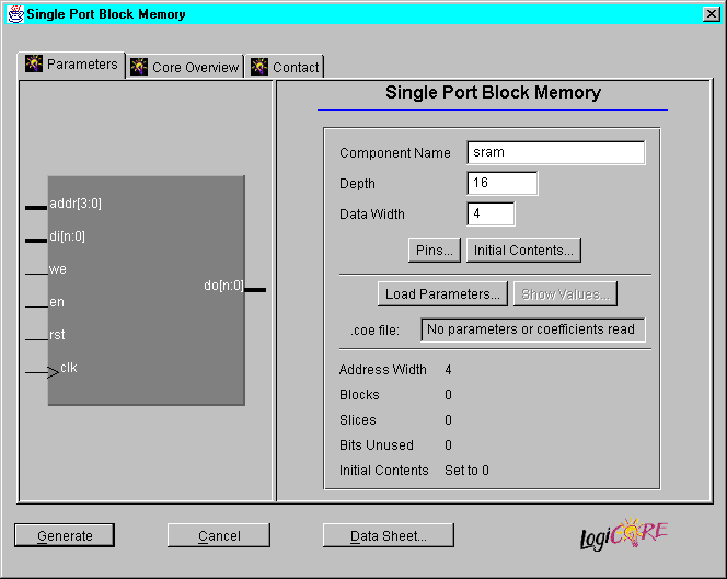
| component_name.coe | ASCII data file defining the coefficient values for FIR filters and initialization values for memory modules | |
| component_name.xco | CORE Generator file containing the parameters used to generate the customized CORE | |
| component_name.edn | EDIF implementation netlist for the CORE | |
| component_name.vho | VHDL template file | |
| component_name.mif | Memory Initialization Module for Virtex Block RAM modules |
----------------------------------------------------------------------

-- This file was created by the Xilinx CORE Generator tool, and     --

-- is (c) Xilinx, Inc. 1998, 1999. No part of this file may be      --

-- transmitted to any third party (other than intended by Xilinx)   --

-- or used without a Xilinx programmable or hardwire device without --

-- Xilinx's prior written permission.                               --

----------------------------------------------------------------------


-- The following code must appear in the VHDL architecture header:


------------- Begin Cut here for COMPONENT Declaration ------ COMP_TAG

component sram

     port (

     addr: IN std_logic_VECTOR(3 downto 0);

     clk: IN std_logic;

     di: IN std_logic_VECTOR(3 downto 0);

     we: IN std_logic;

     en: IN std_logic;

     rst: IN std_logic;

     do: OUT std_logic_VECTOR(3 downto 0));

end component;

-- COMP_TAG_END ------ End COMPONENT Declaration ------------


-- The following code must appear in the VHDL architecture

-- body. Substitute your own instance name and net names.


------------- Begin Cut here for INSTANTIATION Template ----- INST_TAG

your_instance_name : sram

          port map (

               addr => addr,

               clk => clk,

               di => di,

               we => we,

               en => en,

               rst => rst,

               do => do);

-- INST_TAG_END ------ End INSTANTIATION Template ------------


-- The following code must appear above the VHDL configuration

-- declaration. An example is given at the end of this file.


------------- Begin Cut here for LIBRARY Declaration -------- LIB_TAG


-- synopsys translate_off


Library XilinxCoreLib;


-- synopsys translate_on


-- LIB_TAG_END ------- End LIBRARY Declaration ------------


-- The following code must appear within the VHDL top-level

-- configuration declaration. Ensure that the translate_off/on

-- compiler directives are correct for your synthesis tool(s).


------------- Begin Cut here for CONFIGURATION snippet ------ CONF_TAG


-- synopsys translate_off


     for all : sram use entity XilinxCoreLib.C_MEM_SP_BLOCK_V1_0(behavioral)

          generic map(

               c_has_en => 1,

               c_rst_polarity => 1,

               c_clk_polarity => 1,

               c_width => 4,

               c_has_do => 1,

               c_has_di => 1,

               c_en_polarity => 1,

               c_has_we => 1,

               c_has_rst => 1,

               c_address_width => 4,

               c_read_mif => 0,

               c_depth => 16,

               c_pipe_stages => 0,

               c_mem_init_radix => 16,

               c_default_data => "0",

               c_mem_init_file => "sram.mif",

               c_we_polarity => 1,

               c_generate_mif => 0);

     end for;


-- synopsys translate_on


-- CONF_TAG_END ------ End CONFIGURATION snippet ------------


-------------------------------------------------------------

-- Example of configuration declaration...

-------------------------------------------------------------

--

-- <Insert LIBRARY Declaration here>

--

-- configuration <cfg_my_design> of <my_design> is

--     for <my_arch_name>

--         <Insert CONFIGURATION Declaration here>

--     end for;

-- end <cfg_my_design>;

--

-- If this is not the top-level design then in the next level up, the following text

-- should appear at the end of that file:

--

-- configuration <cfg> of <next_level> is

--     for <arch_name>

--           for all : <my_design> use configuration <cfg_my_design>;

--           end for;

--     end for;

-- end <cfg>;

--
Note: Instead of opening a second sesssion, you could use Edit ![]() Insert File from the HDL Editor tool bar to insert the file into the current HDL Editor session.
Insert File from the HDL Editor tool bar to insert the file into the current HDL Editor session.
Note: When the design is synthesized, a warning is generated that the CORE module is unexpanded. Modules instantiated as black boxes are not elaborated and optimized. The warning message is just reflecting the black box instantiation.
Note: The instantiated module must be in the same directory as the HDL code in which it is instantiated.
This section explains how to instantiate a CORE component into a Verilog design using Foundation.
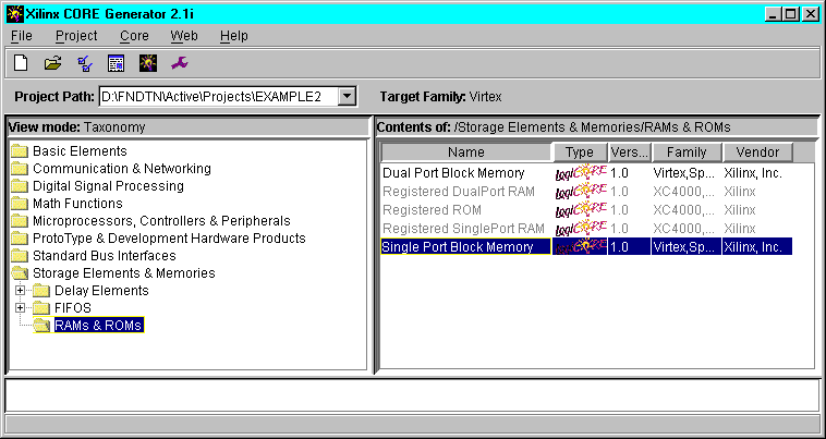
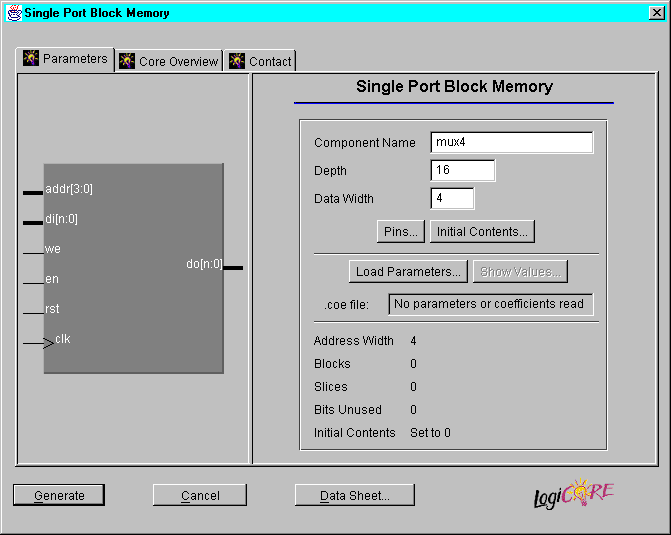
| component_name.coe | ASCII data file defining the coefficient values for FIR filters and initialization values for memory modules | |
| component_name.xco | CORE Generator file containing the parameters used to generate the customized CORE | |
| component_name.edn | EDIF implementation netlist for the CORE | |
| component_name.veo | Verilog template file | |
| component_name.mif | Memory Initialization Module for Virtex Block RAM modules |
/*******************************************************************

* This file was created by the Xilinx CORE Generator tool, and     *

* is (c) Xilinx, Inc. 1998, 1999. No part of this file may be      *

* transmitted to any third party (other than intended by Xilinx)   *

* or used without a Xilinx programmable or hardwire device without *

* Xilinx's prior written permission.                               *

*******************************************************************/


// The following line must appear at the top of the file in which

// the core instantiation will be made. Ensure that the translate_off/_on

// compiler directives are correct for your synthesis tool(s)


//----------- Begin Cut here for LIBRARY inclusion --------// LIB_TAG


// synopsys translate_off


`include "XilinxCoreLib/C_MEM_SP_BLOCK_V1_0.v"


// synopsys translate_on


// LIB_TAG_END ------- End LIBRARY inclusion --------------


// The following code must appear after the module in which it

// is to be instantiated. Ensure that the translate_off/_on compiler

// directives are correct for your synthesis tool(s).


//----------- Begin Cut here for MODULE Declaration -------// MOD_TAG

module mux4 (

     ADDR,

     CLK,

     DI,

     WE,

     EN,

     RST,

     DO);


input [3 : 0] ADDR;

input CLK;

input [3 : 0] DI;

input WE;

input EN;

input RST;

output [3 : 0] DO;


// synopsys translate_off


     C_MEM_SP_BLOCK_V1_0 #(

          4,

          1,

          "0",

          16,

          1,

          0,

          1,

          1,

          1,

          1,

          1,

          "mux4.mif",

          16,

          0,

          0,

          1,

          1,

          4)

     inst (

          .ADDR(ADDR),

          .CLK(CLK),

          .DI(DI),

          .WE(WE),

          .EN(EN),

          .RST(RST),

          .DO(DO));


// synopsys translate_on


endmodule

// MOD_TAG_END ------- End MODULE Declaration -------------


// The following must be inserted into your Verilog file for this

// core to be instantiated. Change the instance name and port connections

// (in parentheses) to your own signal names.


//----------- Begin Cut here for INSTANTIATION Template ---// INST_TAG

mux4 YourInstanceName (

     .ADDR(ADDR),

     .CLK(CLK),

     .DI(DI),

     .WE(WE),

     .EN(EN),

     .RST(RST),

     .DO(DO));

// INST_TAG_END ------ End INSTANTIATION Template ---------
Note: Instead of opening a second sesssion, you could use Edit ![]() Insert File from the HDL Editor tool bar to insert the file into the current HDL Editor session.
Insert File from the HDL Editor tool bar to insert the file into the current HDL Editor session.
Note: When the design is synthesized, a warning is generated that the CORE module is unexpanded. Modules instantiated as black boxes are not elaborated and optimized. The warning message is just reflecting the black box instantiation.
Note: The instantiated module must be in the same directory as the HDL code in which it is instantiated.
This section explains how to instantiate an XNF file as a black box in a VHDL or Verilog design.
SYM, current_state_reg<4>, DFF, LIBVER=2.0.0

PIN, D, I, next_state<4>, ,

PIN, C, I, N10, ,

PIN, Q, O, current_state<4>, ,

END

SIG, current_state<4>

SIG, CLK, I, ,

SIG, DATA, I, ,

SIG, SYNCFLG, O, ,
Note: When the design is synthesized, a warning is generated that the XNF module is unexpanded. Modules instantiated as black boxes are not elaborated and optimized. The warning message is just reflecting the black box instantiation. Expansion of the XNF module takes place during the Translation stage of the Implementation phase.
The instantiated module must be in the same directory as the HDL code in which it is instantiated.