|
|
|
|
|
|
To take advantage of cross-boundary optimization and top-down synthesis methodology, you can use the HDL flow instead of the Schematic flow for top-level schematic designs with underlying HDL macros. In the HDL flow, your entire design is synthesized and optimized resulting in overall design performance improvement. The HDL flow is recommended for schematic top-level designs that contain underlying HDL macros. Used in this way, the tool behaves like an HDL block level diagram editor.
The following sections describe the HDL flow procedure for top-level schematic designs containing underlying HDL macros.
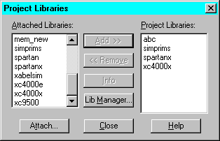
In an HDL flow project, the device family is not selected until the design is synthesized. Therefore, you need to add a Xilinx library manually to make the Xilinx components available for schematic entry.

Note: If you want to create a top-level schematic to act only as a block diagram for your HDL designs, you do not need to add a schematic library.
Use the following procedure to create a macro from an HDL file (or State Machine) for use in a schematic.
Note: If the Create Macro or Update Macro option is not available, check whether the HDL file has already been “added” to the project. If it is listed in the Files tab of the Project Manager, it is currently “added” to the project. Remove the file from the project by selecting it and choosing Document ![]() Remove. You can now create the macro. The file will be automatically added to the project when the entire design is analyzed later.
Remove. You can now create the macro. The file will be automatically added to the project when the entire design is analyzed later.
This section lists the basic steps for creating a schematic and generating a netlist from it.


Note: If the HDL macros in the schematic have lower levels of hierarchy or use user-defined libraries, you must add the files for the lower levels to your project manually. Select Document ![]() Add from the Project Manager to add the files. Foundation needs access to all the design files before synthesis can occur.
Add from the Project Manager to add the files. Foundation needs access to all the design files before synthesis can occur.
When a schematic is added to the project or when Foundation analyzes the schematic portion of the design, the schematic is netlisted into one of three formats: VHDL, XNF, or EDIF. (By default, VHDL is used.)
From the Project Manager, select Synthesis ![]() Options and choose a netlist format in the “Export schematics to” section based on the following criteria.
Options and choose a netlist format in the “Export schematics to” section based on the following criteria.
Synthesize the design in the same manner you would a top-level HDL design.
Foundation links all the project files and synthesizes the design using the top-down methodology.
HDL files from the schematic are added to the project when the schematic is analyzed. All HDL and State Machine files for which schematic macros were created are added to the Files tab. You may open and edit these files by double clicking on them in the Files tab. However, you can only update the HDL macros by opening them from the Schematic Editor and then selecting Project ![]() Update Macro.
Update Macro.
For more information on completing an HDL flow project, refer to the “Synthesizing the Design”through the “Programming the Device” sections under the “All-HDL Designs” section.