Foundation Series 2.1i User GuideChapter 6: HDL Design Entry and Synthesis
Synthesis of HDL Modules
Foundation projects can be either Schematic Flow or HDL Flow projects. Many of the HDL editing and synthesis operations described in this section are the same for both flows; however, differences do exist and are noted where appropriate. This section describes how to synthesize your design without also continuing through implementation.
Schematic Flow Methodology
In a Schematic Flow project, VHDL and Verilog modules can only be underlying modules in a top-level schematic design. Each HDL file is synthesized and optimized separately. Top-level ABEL designs and ABEL State Machine designs are only supported in the Schematic Flow.
The Schematic Flow methodology can be beneficial if you have a few HDL blocks in an otherwise schematic environment. In this case, you synthesize each individual HDL module separately.
Following is the general procedure to synthesize HDL Modules in Schematic Flow Projects.
- Open the HDL file in the HDL Editor. This can be done by the methods listed in the “HDL File Selection” section or by double clicking on the .vhd (VHDL) or .v (Verilog) file in the Project Manager.
- Select Synthesis
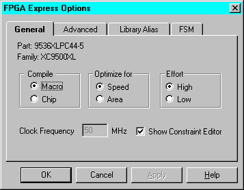
 Options to access the FPGA Express Options window. In the General tab, select the optimization options for the module.

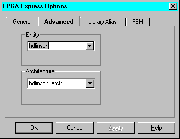
- Click on the Advanced tab. Select the top-level entity and architecture, and click OK.

- To synthesize the module and create a symbol, choose Project
 Create Macro from the HDL Editor window.
- Repeat step 4 for each HDL module.
HDL Flow Methodology
In an HDL Flow project, all top-level VHDL and Verilog files and schematics are exported to the synthesis tool and optimized. Pre-Implementation constraint editing, cross-boundary optimization, and auto I/O buffer insertion are only available in an HDL Flow Project.
The HDL Flow approach provides an easier method of compilation. It requires only a single synthesis action for all HDL modules. In addition, this method includes optional cross-boundary optimization of the entire design, editing of constraints prior to implementation, and auto I/O buffer insertion.
Following is the general procedure to synthesize HDL modules in HDL Flow Projects.
- Be sure that all HDL files are added to the project. See the “Adding the File to the Project” section for instructions on adding files to a project. Underlying HDL macros in top-level schematics in HDL projects are an exception to this; files for those HDL macros are added automatically during synthesis.
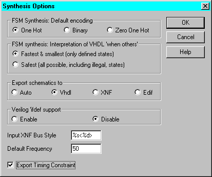
- From the Project Manager window, set the global synthesis options by selecting Synthesis
 Options to open the Synthesis Options dialog box.

In the Synthesis Options dialog box, set the Default FSM Encoding style, XNF Bus Style, and Default Frequency. Check the Export Timing Constraint box if you want to have timing and pin location constraints entered after the elaboration step to be automatically exported to place and route tools.
For FSM Encoding style, use the following guidelines for best results.
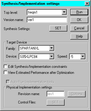
- To synthesize the design, click the Synthesis button on the Flow tab. This opens the Synthesis/Implementation dialog box.

- In the Synthesis/Implementation dialog box, you can do the following.
- Select the name of the top-level entity or module from which processing of the design hierarchy should begin
- Enter a version name
- Select the target device
- Choose to edit constraints after elaboration. This option opens the Express Constraints Editor before the design is optimized by the synthesis engine.
- Choose to view the estimated performance after optimization spreadsheets. This opens the Express Time Tracker and displays the design's pre-implementation timing estimates.
- Click SET to access the Synthesis Setting and modify the synthesis settings as desired
When ready, click Run to synthesize the design.


